The rapid development of electric vehicle (EV) and hybrid electric vehicle (HEV) has put forward higher requirements on the energy density and cycle life of lithium-ion batteries. Cathode material is one of the most critical parts in determining the performance of lithium-ion batteries. Lithium-rich manganese-based layered oxides (LMLOs) are considered to be the most promising cathode materials for next-generation power batteries due to their high specific capacity (>250 mA·h/g), high work voltage, low cost and high safety. However, low initial coulombic efficiency, severe voltage fading, and poor cycle and rate performance prevent their practical application. This review summarizes the causes of the above-mentioned problems, including irreversible oxygen release, irreversible transformation from layered structure to spinel phase, and migration and valence change of transition metal ions. What’s more, some typical solutions reported by domestic and overseas researchers in recent years are also summarized from the following four aspects: surface coating, surface/bulk doping, crystal-facet control, and surface integrated structure, respectively.
ZHANG Zuhao. Challenges and solutions of lithium-rich manganese-based layered oxide cathode materials[J]. Energy Storage Science and Technology, 2021, 10(2): 408-424
Fig. 1
The Crystal structure of the (a) LiMO2(Rm)、(b)Li2MnO3(C2/m) viewed from the [100] crystallographic direction[36]; (c) STEM-HAADF image of the 45 cycled Li1.2Ni0.2Mn0.6O2[37]; (d) Schematic diagram showing the charge/discharge curves of a typical LMLOs with the evolution of structure during cycling[43]
Fig. 2
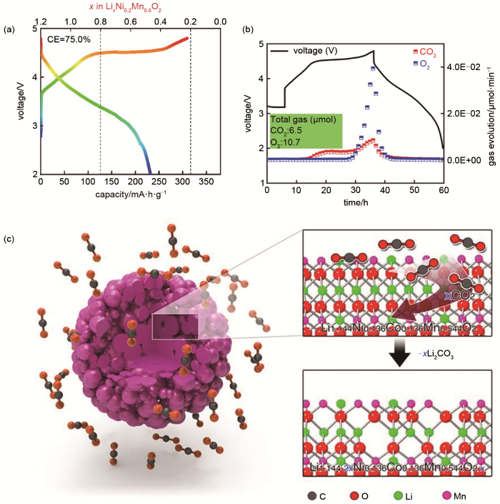
(a) the first charge-discharge curve of Li1.2Mn0.6Ni0.2O2[46]; (b) the first cycle voltage profiles and gas evolution rates of Li1.2Mn0.6Ni0.2O2 electrode[46]; (c) schematic of gas-solid interface reaction (GSIR) between Li-rich layered oxides and carbon dioxide[30]
Fig. 3
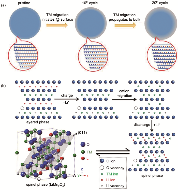
(a) schematic describing the TM migration mechanism in Li1.2Ni0.2Ru0.6O2 upon cycling, where blue and orange indicate transition metal and lithium ions, respectively[53]; (b) schematic view of structural transformation from layered to spinel phase upon cycling for Li1.2Ni0.2Mn0.6O2 active materials[14]
Fig. 4
Redox couple evolution of Li1.2Ni0.15Co0.1Mn0.55O2 during cycling[15]. (a) the contribution towards the discharge capacity from Ni, Co, Mn and O redox at various cycles; (b) effects of electronic structure changeon the Fermi level; (c) diagram of the correlation between redox couple and energy level of each element
Fig. 5
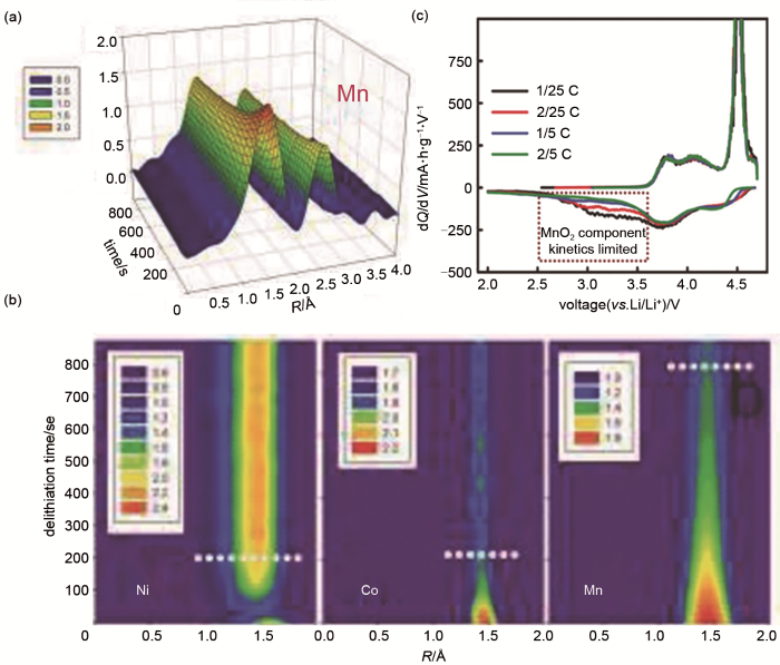
(a) magnitude of the Fourier transformed Mn K-edge spectra of Li1.2Ni0.15Co0.1Mn0.55O2 collected during 5 V constant voltage charging[16]; (b) projection view of the corresponding Ni-O, Co-O, and Mn-O peak magnitudes of the Fourier transformed K-edge spectra as functions of charging time[16]; (c) the dQ/dV curves of cathode material Li[Li0.2Ni0.2Mn0.6]O2 at various current density[18]
Fig. 6
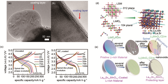
(a) the TEM image of the AlF3 coating on Li1.2Ni0.15Co0.10Mn0.55O2[64]; (b) higher magnification TEM image showing the AlF3 coating layer on the LMR cathode[64] ; (c) corresponding charging and discharging curve of uncoated material and AlF3-coated material during cycling[64]; (d) the mechanism of LSM-coated LM[65], (e) schematic of structure evolution of pristine LM and LSM-coated sample during electrochemical cycling[65]
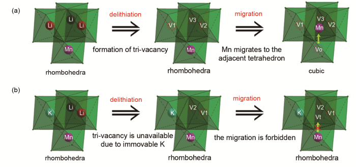
Fig. 7
Schematic diagrams of the phase evolution routes for (a) pristine sample and (b) potassium-doped (V1, V2 and V3 stand for vacancies in lithium layer; Vt stands for tetrahedral vacancy and Vo for octahedral vacancy) [75]
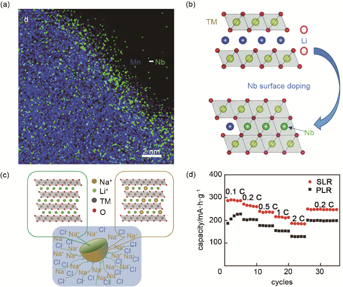
Fig. 8
(a) the schematic process of surface doping and the Nb-enhanced surface structure[80]; (b) the EDS mapping of Mn and Nb for the LMR-Nb sample[80];(c) Schematic illustration of the structure design of gradient surface Na+ doping Li-rich material[82]; (d) The rate performance of pristine Li-rich material (PLR) and Na+ doped Li-rich material (SLR) [82]
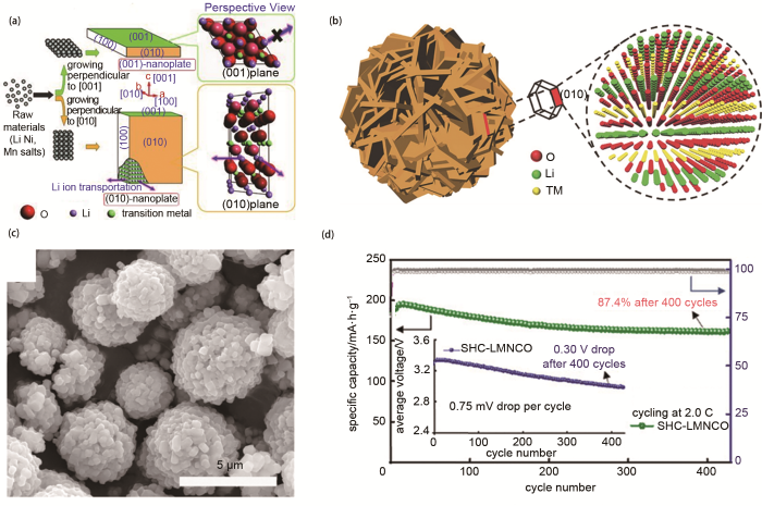
Fig. 9
(a) schematic illustration of two kinds of nanoplates and the microstructure of their surfaces[84]; (b) schematic illustration of Li1.2Mn0.6Ni0.2O2[86] ; (c) SEM image of hierarchical Li1.2Mn0.54Ni0.13Co0.13O2 spheres[87]; (d) cycling performance of LMLOs at 2C, inset is the average voltage plots upon cycling at 2C[26]
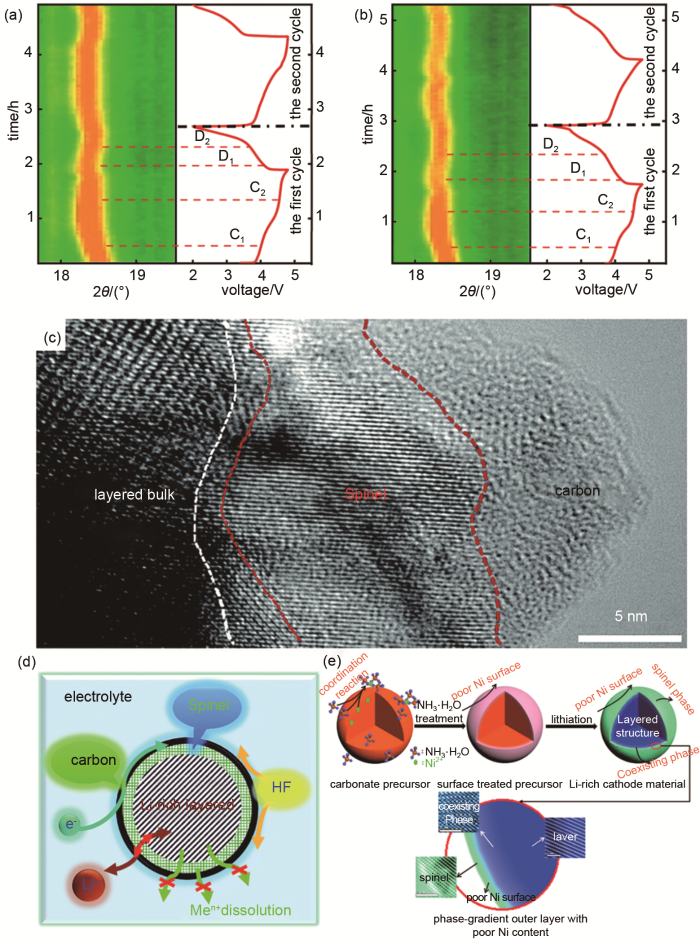
Fig. 10
(a)~(b) in situ XRD image of LMLOs which before and after modification[90]; (c) high-resolution transmission electron miscroscopy (HRTEM) image of the layered@spinel@carbon heterostructure in LMLOs [32]; (d) schematic view of the layered@spinel@carbon heterostructure[32]; (e) schematic diagram of the formation process and design strategy of Li-rich layered oxide particle with phase gradient outer layer accompanied by poor nickel content[91]
KALLURI S, YOON M, JO M, et al. Surface engineering strategies of layered LiCoO2 cathode material to realize high-energy and high-voltage Li-ion cells[J]. Advanced Energy Materials, 2017, 7 (1): doi: 10.1002/aenm.201601507.
ZHANG Z K, MCNALL B, KANAGARAJ A B, et al. Electrochemical characterization of LiMn2O4 nanowires fabricated by sol-gel for lithium-ion rechargeable batteries[J]. Materials Letters, 2020, 273: doi: 10.1016/j.matlet.2020.127923.
LUO D, FANG S H, TIAN Q H, et al. Uniform LiMO2 assembled microspheres as superior cycle stability cathode materials for high energy and power Li-ion batteries[J]. Journal of Materials Chemistry A, 2015, 3 (44): 22026-22030.
WANG J, HE X, PAILLARD E, et al. Lithium‐ and manganese‐rich oxide cathode materials for high‐energy lithium ion batteries[J]. Advanced Energy Materials, 2016, 6(21): doi: 10.1002/aenm.201600906.
NUMATA K, SAKAKI C, YAMANAKA S. Synthesis and characterization of layer structured solid solutions in the system of LiCoO2-Li2MnO3[J]. Solid State Ionics, 1999, 117(3/4): 257-263.
NUMATA K, SAKAKI C, YAMANAKA S. Synthesis of solid solutions in a system of LiCoO2-Li2MnO3 for cathode material of secondary lithium batteries[J]. Chemistry Letters, 1997, 8(8): 725-726.
ZUO Y, LI B, JIANG N, et al. A high‐capacity O2‐type Li‐rich cathode material with a single‐layer Li2MnO3 superstructure[J]. Advanced Materials, 2018, 30 (16): doi: 10.1002/adma.201707255.
ZHENG J, MYEONG S, CHO W, et al. Li‐ and Mn‐rich cathode materials: Challenges to commercialization[J]. Advanced Energy Materials, 2016, 7 (6): doi: 10.1002/aenm.201601284.
KLEINER K, STREHLE B, BAKER A R, et al. Origin of high capacity and poor cycling stability of Li-rich layered oxides: A long-duration in situ synchrotron powder diffraction study[J]. Chemistry of Materials, 2018, 30(11): 3656-3667.
XIAO B, WANG P B, ZHANG B, et al. Effect of MgO and TiO2 coating on the electrochemical performance of Li‐rich cathode materials for lithium‐ion batteries[J]. Energy Technology, 2019, 7(8): doi: 10.1002/ente.201800829.
CHONG S, CHEN Y, YAN W, et al. Suppressing capacity fading and voltage decay of Li-rich layered cathode material by a surface nano-protective layer of CoF2 for lithium-ion batteries[J]. Journal of Power Sources, 2016, 332: 230-239.
HU E, YU X, LIN R, et al. Evolution of redox couples in Li-and Mn-rich cathode materials and mitigation of voltage fade by reducing oxygen release[J]. Nature Energy, 2018, 3(8): 690-698.
ATES M N, MUKERJEE S, ABRAHAM K M. A Li-rich layered cathode material with enhanced structural stability and rate capability for Li-on batteries[J]. Journal of the Electrochemical Society, 2014, 161(3): A355-A363.
ZHENG J, SHI W, GU M, et al. Electrochemical kinetics and performance of layered composite cathode material Li[Li0.2Ni0.2Mn0.6]O2[J]. Journal of the Electrochemical Society, 2013, 160(11): A2212-A2219.
YANG J, LI P, ZHONG F, et al. Suppressing voltage fading of Li‐rich oxide cathode via building a well‐protected and partially‐protonated surface by polyacrylic acid binder for cycle‐stable Li‐ion batteries[J]. Advanced Energy Materials, 2020, 10(15): doi: 10.1002/aenm.201904264.
XU Z, CI L, YUAN Y, et al. Potassium prussian blue-coated Li-rich cathode with enhanced lithium ion storage property[J]. Nano Energy, 2020: doi: 10.1016/j.nanoen.2020.104942.
DUAN J, TANG W, WANG R, et al. Inhibited voltage decay and enhanced electrochemical performance of the Li-rich layered Li1.2Mn0.54Ni0.13Co0.13O2 cathode material by CeAlOδ surface coating modification[J]. Applied Surface Science, 2020, 521: doi: 10.1016/j.apsusc.2020.146504.
SU Y, YUAN F, CHEN L, et al. Enhanced high-temperature performance of Li-rich layered oxide via surface heterophase coating[J]. Journal of Energy Chemistry, 2020, 51: 39-47.
LIU P, ZHANG H, HE W, et al. Lithium deficiencies engineering in Li-rich layered oxide Li1.098Mn0.533Ni0.113Co0.138O2 for high-stability cathode[J]. Journal of the American Chemical Society, 2019, 141 (27): 10876-10882
DONG S, ZHOU Y, HAI C, et al. Understanding electrochemical performance improvement with Nb doping in lithium-rich manganese-based cathode materials[J]. Journal of Power Sources, 2020, 462: doi: 10.1016/j.jpowsour.2020.228185.
LIU S, LIU Z, SHEN X, et al. Surface doping to enhance structural integrity and performance of Li-rich layered oxide[J]. Advanced Energy Materials, 2018, 8(31): doi: 10.1002/aenm.201802105.
LIU Y, WANG J, WU J, et al. 3D cube‐maze‐like Li‐rich layered cathodes assembled from 2D porous nanosheets for enhanced cycle stability and rate capability of lithium‐ion batteries[J]. Advanced Energy Materials, 2019, 10(5): doi: 10.1002/aenm.201903139.
MA Y, LIU P, XIE Q, et al. Double-shell Li-rich layered oxide hollow microspheres with sandwich-like carbon@spinel@layered@spinel@carbon shells as high-rate lithium ion battery cathode[J]. Nano Energy, 2019, 59: 184-196.
WU B, YANG X, JIANG X, et al. Synchronous tailoring surface structure and chemical composition of Li-rich-layered oxide for high-energy lithium-ion batteries[J]. Advanced Functional Materials, 2018, 28(37): doi: 10.1002/adfm.201803392.
LUO D, FANG S, YANG L, et al. Preparation of layered-spinel microsphere/reduced graphene oxide cathode materials for ultrafast charge-discharge lithium-ion batteries[J]. ChemSusChem, 2017, 10(24): 4845-4850.
XIA Q, ZHAO X, XU M, et al. A Li-rich layered@spinel@carbon heterostructured cathode material for high capacity and high rate lithium-ion batteries fabricated via an in situ synchronous carbonization-reduction method[J]. Journal of Materials Chemistry A, 2015, 3(7): 3995-4003.
CHEN L, SU Y, CHEN S, et al. Hierarchical Li1.2Ni0.2Mn0.6O2 nanoplates with exposed {010} planes as high-performance cathode material for lithium-ion batteries[J]. Advanced Materials, 2014, 26(39): 6756-6760.
DING X, LUO D, CUI J, et al. An ultra-long-life lithium-rich Li1.2Mn0.6Ni0.2O2 cathode by three-in-one surface modification for lithium-ion batteries[J]. Angewandte Chemie International Edition, 2020, 59(20): 7778-7782.
ZHU Z, YU D, YANG Y, et al. Gradient Li-rich oxide cathode particles immunized against oxygen release by a molten salt treatment[J]. Nature Energy, 2019, 4(12): 1049-1058.
YU H, ZHOU H. High-energy cathode materials (Li2MnO3-LiMO2) for lithium-ion batteries[J]. The Journal of Physical Chemistry Letters, 2013, 4(8): 1268-1280.
YAN P, NIE A, ZHENG J, et al. Evolution of lattice structure and chemical composition of the surface reconstruction layer in Li1.2Ni0.2Mn0.6O2 cathode material for lithium ion batteries[J]. Nano Letters, 2015, 15(1): 514-522.
CROY J R, BALASUBRAMANIAN M, GALLAGHER K G, et al. Review of the US department of energy's "deep dive" effort to understand voltage fade in Li- and Mn-rich cathodes[J]. Accounts of Chemical Research, 2015, 48(11): 2813-2821.
THACKERAY M M, JOHNSON C S, VAUGHEY J T, et al. Advances in manganese-oxide 'composite' electrodes for lithium-ion batteries[J]. Journal of Materials Chemistry, 2005, 15(23): 2257-2267.
KANG S H, KEMPGENS P, GREENBAUM S, et al. Interpreting the structural and electrochemical complexity of 0.5Li2MnO3·0.5LiMO2 electrodes for lithium batteries (M = Mn0.5-xNi0.5-xCo2x, 0 ≤ x ≤ 0.5)[J]. Journal of Materials Chemistry, 2007, 17(20): 2069-2077.
LANZ P, VILLEVIEILLE C, NOVÁK P. Ex situ and in situ raman microscopic investigation of the differences between stoichiometric LiMO2 and high-energy xLi2MnO3·(1–x)LiMO2 (M = Ni, Co, Mn)[J]. Electrochimica Acta, 2014, 130: 206-212.
JARVIS K A, DENG Z, ALLARD L F, et al. Atomic structure of a lithium-rich layered oxide material for lithium-ion batteries: evidence of a solid solution[J]. Chemistry of Materials, 2011, 23(16): 3614-3621.
Xiao B, Sun X. Surface and subsurface reactions of lithium transition metal oxide cathode materials: An overview of the fundamental origins and remedying approaches[J]. Advanced Energy Materials, 2018, 8(29): doi: 10.1002/aenm.201802057.
XIAO B, LIU H, CHEN N, et al. Size-mediated recurring spinel sub-nanodomains in Li- and Mn-rich layered cathode materials[J]. Angewandte Chemie International Edition, 2020, 59(34): 14313-14320.
ENYUAN H, XIQIAN Y, RUOQIAN L, et al. Evolution of redox couples in Li- and Mn-rich cathode materials and mitigation of voltage fade by reducing oxygen release[J]. Nature Energy, 2018, 3(8): 690-698.
KLEINER, KARIN, STREHLE, et al. Origin of high capacity and poor cycling stability of Li-rich layered oxides: a long-duration in situ synchrotron powder diffraction study[J]. Chemistry of Materials, 2018, 30(11): 3656-3667.
LUO K, ROBERTS M R, HAO R, et al. Charge-compensation in 3d-transition-metal-oxide intercalation cathodes through the generation of localized electron holes on oxygen[J]. Nature Chemistry, 2016, 8(7): 684-691.
PEREZ A J, JACQUET Q, BATUK D, et al. Approaching the limits of cationic and anionic electrochemical activity with the Li-rich layered rocksalt Li3IrO4[J]. Nature Energy, 2017, 2(12): 954-962.
ROZIER P, TARASCON J M. Review-Li-rich layered oxide cathodes for next-generation Li-ion batteries: Chances and challenges[J]. Journal of the Electrochemical Society, 2015, 162(14): A2490-A2499.
ZHENG J, GU M, XIAO J, et al. Corrosion/fragmentation of layered composite cathode and related capacity/voltage fading during cycling process[J]. Nano Letters, 2013, 13(8): 3824 -3830.
LI N, HWANG S, SUN M, et al. Unraveling the voltage decay phenomenon in Li-rich layered oxide cathode of no oxygen activity[J]. Advanced Energy Materials, 2019, 9(47): doi: 10.1002/aenm.201902258.
NAYAK P K, ERICKSON E M, SCHIPPER F, et al. Review on challenges and recent advances in the electrochemical performance of high capacity Li‐ and Mn‐rich cathode materials for Li‐ion batteries[J]. Advanced Energy Materials, 2018, 8(8): doi: 10.1002/aenm.201702397.
NAYAK P K, GRINBLAT J, LEVI E, et al. Remarkably improved electrochemical performance of Li- and Mn-rich cathodes upon substitution of Mn with Ni[J]. ACS Applied Materials & Interfaces, 2017, 9(5): 4309-4319.
SETENI B, RAPULENYANE N, NGILA J C, et al. Coating effect of LiFePO4 and Al2O3 on Li1.2Mn0.54Ni0.13Co0.13O2 cathode surface for lithium ion batteries[J]. Journal of Power Sources, 2017, 353: 210-220.
RASTGOO-DEYLAMI M, JAVANBAKHT M, OMIDVAR H. Enhanced performance of layered Li1.2Mn0.54Ni0.13Co0.13O2 cathode material in Li-ion batteries using nanoscale surface coating with fluorine-doped anatase TiO2[J]. Solid State Ionics, 2019, 331: 74-88.
XIE Y, CHEN S, LIN Z, et al. Enhanced electrochemical performance of Li-rich layered oxide, Li1.2Mn0.54Co0.13Ni0.13O2, by surface modification derived from a MOF-assisted treatment[J]. Electrochemistry Communications, 2019, 99: 65-70.
JIN Y, XU Y, SUN X, et al. Electrochemically active MnO2 coated Li1.2Ni0.18Co0.04Mn0.58O2 cathode with highly improved initial coulombic efficiency[J]. Applied Surface Science, 2016, 384: 125-134.
GUO S, YU H, LIU P, et al. Surface coating of lithium-manganese-rich layered oxides with delaminated MnO2 nanosheets as cathode materials for Li-ion batteries[J]. Journal of Materials Chemistry A, 2014, 2(12): 4422-4428.
HAN E, LI Y, ZHU L, et al. The effect of MgO coating on Li1.17Mn0.48Ni0.23Co0.12O2 cathode material for lithium ion batteries[J]. Solid State Ionics, 2014, 255: 113-119.
ZHAO T, LI L, CHEN R, et al. Design of surface protective layer of LiF/FeF3 nanoparticles in Li-rich cathode for high-capacity Li-ion batteries[J]. Nano Energy, 2015, 15: 164-176.
ZHENG J, GU M, XIAO J, et al. Functioning mechanism of AlF3 coating on the Li- and Mn-rich cathode materials[J]. Chemistry of Materials, 2014, 26(22): 6320-6327.
HU S, LI Y, CHEN Y, et al. Insight of a phase compatible surface coating for long‐durable Li‐rich layered oxide cathode[J]. Advanced Energy Materials, 2019, 9(34): doi: 10.1002/aenm.201901795.
BAK S M, SHADIKE Z, LIN R Q, et al. In situ/operando synchrotron-based X-ray techniques for lithium-ion battery research[J]. NPG Asia Materials, 2018, 10(7): 563-580.
HUIMIAN L, HUAJUN G, ZHIXING W, et al. Improving rate capability and decelerating voltage decay of Li-rich layered oxide cathodes by chromium doping[J]. International Journal of Hydrogen Energy, 2018, 43(24): 11109-11119.
LIU Y, ZHANG Z, GAO Y, et al. Mitigating the voltage decay and improving electrochemical properties of layered-spinel Li1.1Ni0.25Mn0.75O2.3 cathode material by Cr doping[J]. Journal of Alloys and Compounds, 2016, 657: 37-43.
WANG Y, YANG Z, QIAN Y, et al. New insights into improving rate performance of lithium‐rich cathode material[J]. Advanced Materials, 2015, 27(26): 3915-3920.
YAN W, XIE Y, JIANG J, et al. Enhanced rate performance of Al-doped Li-rich layered cathode material via nucleation and post-solvothermal method[J]. ACS Sustainable Chemistry & Engineering, 2018, 6(4): 4625-4632.
MA Q, LI R, ZHENG R, et al. Improving rate capability and decelerating voltage decay of Li-rich layered oxide cathodes via selenium doping to stabilize oxygen[J]. Journal of Power Sources, 2016, 331: 112-121.
YU R, WANG G, LIU M, et al. Mitigating voltage and capacity fading of lithium-rich layered cathodes by lanthanum doping[J]. Journal of Power Sources, 2016, 335: 65-75.
CHEN H, HU Q, HUANG Z, et al. Synthesis and electrochemical study of Zr-doped Li[Li0.2Mn0.54Ni0.13Co0.13]O2 as cathode material for Li-ion battery[J]. Ceramics International, 2016, 42(1): 263-269.
ZHENG Z, GUO X D, ZHONG Y J, et al. Host structural stabilization of Li1.232Mn0.615Ni0.154O2 through K-doping attempt: toward superior electrochemical performances[J]. Electrochimica Acta, 2016, 188: 336-343.
LI Q, LI G, FU C, et al. K+-doped Li1.2Mn0.54Co0.13Ni0.13O2: a novel cathode material with an enhanced cycling stability for lithium-ion batteries[J]. ACS Applied Materials & Interfaces, 2014, 6(13): 10330-10341.
NING D, ZHENG L, ZHANG Q, et al. Improving the electrochemical performances of Li-rich Li1.20Ni0.13Co0.13Mn0.54O2 through a cooperative doping of Na+ and PO43- with Na3PO4[J]. Journal of Power Sources, 2018, 375: 1-10.
LIU D, FAN X, LI Z, et al. A cation/anion co-doped Li1.12Na0.08Ni0.2Mn0.6O1.95F0.05 cathode for lithium ion batteries[J]. Nano Energy, 2019, 58: 786-796.
ZHOU H, GUAN H, YIN C, et al. A potassium/chloride ion co-doped cathode material Li1.18K0.02Ni0.2Mn0.6O1.98Cl0.02 with enhanced electrochemical performance for lithium ion batteries[J]. Journal of Materials Science Materials in Electronics, 2019, 31 (1) : 572-580.
LIU Y, HE B, LI Q, et al. Relieving capacity decay and voltage fading of Li1.2Ni0.13Co0.13Mn0.54O2 by Mg2+ and PO43- dual doping[J]. Materials Research Bulletin, 2020, 130: doi: 10.1016/j.materresbull.2020.110923.
LIU S, LIU Z, SHEN X, et al. Surface doping to enhance structural integrity and performance of Li‐rich layered oxide[J]. Advanced Energy Materials, 2018, 8(31): doi: 10.1002/aenm.201802105.
QING R P, SHI J L, XIAO D D, et al. Enhancing the kinetics of Li‐rich cathode materials through the pinning effects of gradient surface Na+ doping[J]. Advanced Energy Materials, 2016, 6(6): doi: 10.1002/aenm.201501914.
ZHAO Y, LIU J, WANG S, et al. Surface structural transition induced by gradient polyanion‐doping in Li‐rich layered oxides: Implications for enhanced electrochemical performance[J]. Advanced Functional Materials, 2016, 26(26): 4760-4767.
WEI G Z, LU X, KE F S, et al. Crystal habit-tuned nanoplate material of Li[Li1/3-2x/3NixMn2/3-x/3]O for high-rate performance lithium-ion batteries[J]. Advanced Materials, 2010, 22(39): 4364-4367.
CHEN L, SU Y, CHEN S, et al. Hierarchical Li1.2Ni0.2Mn0.6O2 nanoplates with exposed {010} planes as high-performance cathode material for lithium-ion batteries[J]. Advanced Materials, 2014, 26(39): 6756-6760.
ZHANG L, LI N, WU B, et al. Sphere-shaped hierarchical cathode with enhanced growth of nanocrystal planes for high-rate and cycling-stable Li-ion batteries[J]. Nano Letters, 2015, 15(1): 656-661.
WEI W, CHEN L, PAN A, et al. Roles of surface structure and chemistry on electrochemical processes in lithium-rich layered oxide cathodes[J]. Nano Energy, 2016, 30: 580-602.
XU B, FELL C R, CHI M, et al. Identifying surface structural changes in layered Li-excess nickel manganese oxides in high voltage lithium ion batteries: a joint experimental and theoretical study[J]. Energy & Environmental Science, 2011, 4(6): 2223-2233.
MA Y, LIU P, XIE Q, et al. Double-shell Li-rich layered oxide hollow microspheres with sandwich-like carbon@spinel@layered@spinel@carbon shells as high-rate lithium ion battery cathode[J]. Nano Energy, 2019, 59: 184-196.
WU B, YANG X, JIANG X, et al. Synchronous tailoring surface structure and chemical composition of Li-rich-layered oxide for high-energy lithium-ion batteries[J]. Advanced Functional Materials, 2018, 28(37): doi: 10.1002/adfm.201803392.
LIN Z, LUO D, DING X, et al. Accurate control of initial coulombic efficiency for Li-rich Mn-based layered oxides by surface multicomponent integration[J]. Angewandte Chemie International Edition, 2020, doi: 10.1002/anie.202010531.
MCCALLA E, ABAKUMOV A M, SAUBANERE M, et al. Visualization of O-O peroxo-like dimers in high-capacity layered oxides for Li-ion batteries[J]. Science, 2015, 350(6267): 1516-1521.
LEE J, URBAN A, LI X, et al. Unlocking the potential of cation-disordered oxides for rechargeable lithium batteries[J]. Science, 2014, 343(6170): 519-522.
ZHOU Y N, MA J, HU E, et al. Tuning charge-discharge induced unit cell breathing in layer-structured cathode materials for lithium-ion batteries[J]. Nature Communications, 2014, 5: doi:10.1038/ncomms6381.
... [15]:(a) 在不同循环周期时,镍、钴、锰和氧元素对放电比容量的贡献;(b) 电子结构变化对费米能级的影响;(c) 每个元素的能级与氧化还原电对的关系图Redox couple evolution of Li<sub>1.2</sub>Ni<sub>0.15</sub>Co<sub>0.1</sub>Mn<sub>0.55</sub>O<sub>2</sub> during cycling<sup>[<xref ref-type="bibr" rid="R15">15</xref>]</sup>. (a) the contribution towards the discharge capacity from Ni, Co, Mn and O redox at various cycles; (b) effects of electronic structure changeon the Fermi level; (c) diagram of the correlation between redox couple and energy level of each elementFig. 4<strong>2.3</strong> 倍率性能差
... [15]. (a) the contribution towards the discharge capacity from Ni, Co, Mn and O redox at various cycles; (b) effects of electronic structure changeon the Fermi level; (c) diagram of the correlation between redox couple and energy level of each elementFig. 4<strong>2.3</strong> 倍率性能差
... [16];(b) 傅里叶变换K-edge光谱对应的Ni-O,Co-O和Mn-O峰值幅度随充电时间变化的投影图[16];(c) 正极材料Li[Li0.2Ni0.2Mn0.6]O2在不同电流密度下对应的dQ/dV曲线[18](a) magnitude of the Fourier transformed Mn K-edge spectra of Li<sub>1.2</sub>Ni<sub>0.15</sub>Co<sub>0.1</sub>Mn<sub>0.55</sub>O<sub>2</sub> collected during 5 V constant voltage charging<sup>[<xref ref-type="bibr" rid="R16">16</xref>]</sup>; (b) projection view of the corresponding Ni-O, Co-O, and Mn-O peak magnitudes of the Fourier transformed K-edge spectra as functions of charging time<sup>[<xref ref-type="bibr" rid="R16">16</xref>]</sup>; (c) the d<i>Q</i>/d<i>V</i> curves of cathode material Li[Li<sub>0.2</sub>Ni<sub>0.2</sub>Mn<sub>0.6</sub>]O<sub>2</sub> at various current density<sup>[<xref ref-type="bibr" rid="R18">18</xref>]</sup>Fig. 53 解决方法<strong>3.1</strong> 包 覆
... [16];(c) 正极材料Li[Li0.2Ni0.2Mn0.6]O2在不同电流密度下对应的dQ/dV曲线[18](a) magnitude of the Fourier transformed Mn K-edge spectra of Li<sub>1.2</sub>Ni<sub>0.15</sub>Co<sub>0.1</sub>Mn<sub>0.55</sub>O<sub>2</sub> collected during 5 V constant voltage charging<sup>[<xref ref-type="bibr" rid="R16">16</xref>]</sup>; (b) projection view of the corresponding Ni-O, Co-O, and Mn-O peak magnitudes of the Fourier transformed K-edge spectra as functions of charging time<sup>[<xref ref-type="bibr" rid="R16">16</xref>]</sup>; (c) the d<i>Q</i>/d<i>V</i> curves of cathode material Li[Li<sub>0.2</sub>Ni<sub>0.2</sub>Mn<sub>0.6</sub>]O<sub>2</sub> at various current density<sup>[<xref ref-type="bibr" rid="R18">18</xref>]</sup>Fig. 53 解决方法<strong>3.1</strong> 包 覆
... [16]; (b) projection view of the corresponding Ni-O, Co-O, and Mn-O peak magnitudes of the Fourier transformed K-edge spectra as functions of charging time[16]; (c) the dQ/dV curves of cathode material Li[Li0.2Ni0.2Mn0.6]O2 at various current density[18]Fig. 53 解决方法<strong>3.1</strong> 包 覆
... [18](a) magnitude of the Fourier transformed Mn K-edge spectra of Li<sub>1.2</sub>Ni<sub>0.15</sub>Co<sub>0.1</sub>Mn<sub>0.55</sub>O<sub>2</sub> collected during 5 V constant voltage charging<sup>[<xref ref-type="bibr" rid="R16">16</xref>]</sup>; (b) projection view of the corresponding Ni-O, Co-O, and Mn-O peak magnitudes of the Fourier transformed K-edge spectra as functions of charging time<sup>[<xref ref-type="bibr" rid="R16">16</xref>]</sup>; (c) the d<i>Q</i>/d<i>V</i> curves of cathode material Li[Li<sub>0.2</sub>Ni<sub>0.2</sub>Mn<sub>0.6</sub>]O<sub>2</sub> at various current density<sup>[<xref ref-type="bibr" rid="R18">18</xref>]</sup>Fig. 53 解决方法<strong>3.1</strong> 包 覆
... [26](a) schematic illustration of two kinds of nanoplates and the microstructure of their surfaces<sup>[<xref ref-type="bibr" rid="R84">84</xref>]</sup>; (b) schematic illustration of Li<sub>1.2</sub>Mn<sub>0.6</sub>Ni<sub>0.2</sub>O<sub>2</sub><sup>[<xref ref-type="bibr" rid="R86">86</xref>]</sup> ; (c) SEM image of hierarchical Li<sub>1.2</sub>Mn<sub>0.54</sub>Ni<sub>0.13</sub>Co<sub>0.13</sub>O<sub>2</sub> spheres<sup>[<xref ref-type="bibr" rid="R87">87</xref>]</sup>; (d) cycling performance of LMLOs at 2C, inset is the average voltage plots upon cycling at 2C<sup>[<xref ref-type="bibr" rid="R26">26</xref>]</sup>Fig. 9<strong>3.4</strong> 表面集成结构
... [30](a) the first charge-discharge curve of Li<sub>1.2</sub>Mn<sub>0.6</sub>Ni<sub>0.2</sub>O<sub>2</sub><sup>[<xref ref-type="bibr" rid="R46">46</xref>]</sup>; (b) the first cycle voltage profiles and gas evolution rates of Li<sub>1.2</sub>Mn<sub>0.6</sub>Ni<sub>0.2</sub>O<sub>2</sub> electrode<sup>[<xref ref-type="bibr" rid="R46">46</xref>]</sup>; (c) schematic of gas-solid interface reaction (GSIR) between Li-rich layered oxides and carbon dioxide<sup>[<xref ref-type="bibr" rid="R30">30</xref>]</sup>Fig. 2<strong>2.2</strong> 容量和电压衰减
... [32];(d)层状@尖晶石@碳异质结构示意图[32];(e)外层为相梯度且镍含量较低的富锂层状氧化物颗粒形成过程及设计策略示意图[91](a)~(b) in situ XRD image of LMLOs which before and after modification<sup>[<xref ref-type="bibr" rid="R90">90</xref>]</sup>; (c) high-resolution transmission electron miscroscopy (HRTEM) image of the layered@spinel@carbon heterostructure in LMLOs<sup> [<xref ref-type="bibr" rid="R32">32</xref>]</sup>; (d) schematic view of the layered@spinel@carbon heterostructure<sup>[<xref ref-type="bibr" rid="R32">32</xref>]</sup>; (e) schematic diagram of the formation process and design strategy of Li-rich layered oxide particle with phase gradient outer layer accompanied by poor nickel content<sup>[<xref ref-type="bibr" rid="R91">91</xref>]</sup>Fig. 10
... [32];(e)外层为相梯度且镍含量较低的富锂层状氧化物颗粒形成过程及设计策略示意图[91](a)~(b) in situ XRD image of LMLOs which before and after modification<sup>[<xref ref-type="bibr" rid="R90">90</xref>]</sup>; (c) high-resolution transmission electron miscroscopy (HRTEM) image of the layered@spinel@carbon heterostructure in LMLOs<sup> [<xref ref-type="bibr" rid="R32">32</xref>]</sup>; (d) schematic view of the layered@spinel@carbon heterostructure<sup>[<xref ref-type="bibr" rid="R32">32</xref>]</sup>; (e) schematic diagram of the formation process and design strategy of Li-rich layered oxide particle with phase gradient outer layer accompanied by poor nickel content<sup>[<xref ref-type="bibr" rid="R91">91</xref>]</sup>Fig. 10
... [32]; (d) schematic view of the layered@spinel@carbon heterostructure[32]; (e) schematic diagram of the formation process and design strategy of Li-rich layered oxide particle with phase gradient outer layer accompanied by poor nickel content[91]Fig. 10
... [32]; (e) schematic diagram of the formation process and design strategy of Li-rich layered oxide particle with phase gradient outer layer accompanied by poor nickel content[91]Fig. 10
... [36];(c) Li1.2Ni0.2Mn0.6O2循环45次后的高角环形暗场-扫描透射显微镜(STEM-HAADF)图[37];(d) 典型LMLOs的充电/放电曲线以及循环过程中结构的演变示意图[43]<strong>The Crystal structure of the (a) LiMO<sub>2</sub>(<i>R</i></strong><span class="formulaText"><inline-formula><math id="M3"><mover><mrow><mn mathvariant="normal">3</mn></mrow><mo>¯</mo></mover></math></span></inline-formula></span><strong><i>m</i>)</strong>、<strong>(b)Li<sub>2</sub>MnO<sub>3</sub>(<i>C2/m</i>) viewed from the [100] crystallographic direction</strong><sup>[<xref ref-type="bibr" rid="R36">36</xref>]</sup><strong>; (c) STEM-HAADF image of the 45 cycled Li<sub>1.2</sub>Ni<sub>0.2</sub>Mn<sub>0.6</sub>O<sub>2</sub></strong><sup>[<xref ref-type="bibr" rid="R37">37</xref>]</sup><strong>; (d) Schematic diagram showing the charge/discharge curves of a typical LMLOs with the evolution of structure during cycling</strong><sup>[<xref ref-type="bibr" rid="R43">43</xref>]</sup>Fig. 1
... [36]; (c) STEM-HAADF image of the 45 cycled Li1.2Ni0.2Mn0.6O2[37]; (d) Schematic diagram showing the charge/discharge curves of a typical LMLOs with the evolution of structure during cycling[43]Fig. 1
<strong>The Crystal structure of the (a) LiMO<sub>2</sub>(<i>R</i></strong><span class="formulaText"><inline-formula><math id="M3"><mover><mrow><mn mathvariant="normal">3</mn></mrow><mo>¯</mo></mover></math></span></inline-formula></span><strong><i>m</i>)</strong>、<strong>(b)Li<sub>2</sub>MnO<sub>3</sub>(<i>C2/m</i>) viewed from the [100] crystallographic direction</strong><sup>[<xref ref-type="bibr" rid="R36">36</xref>]</sup><strong>; (c) STEM-HAADF image of the 45 cycled Li<sub>1.2</sub>Ni<sub>0.2</sub>Mn<sub>0.6</sub>O<sub>2</sub></strong><sup>[<xref ref-type="bibr" rid="R37">37</xref>]</sup><strong>; (d) Schematic diagram showing the charge/discharge curves of a typical LMLOs with the evolution of structure during cycling</strong><sup>[<xref ref-type="bibr" rid="R43">43</xref>]</sup>Fig. 1
<strong>The Crystal structure of the (a) LiMO<sub>2</sub>(<i>R</i></strong><span class="formulaText"><inline-formula><math id="M3"><mover><mrow><mn mathvariant="normal">3</mn></mrow><mo>¯</mo></mover></math></span></inline-formula></span><strong><i>m</i>)</strong>、<strong>(b)Li<sub>2</sub>MnO<sub>3</sub>(<i>C2/m</i>) viewed from the [100] crystallographic direction</strong><sup>[<xref ref-type="bibr" rid="R36">36</xref>]</sup><strong>; (c) STEM-HAADF image of the 45 cycled Li<sub>1.2</sub>Ni<sub>0.2</sub>Mn<sub>0.6</sub>O<sub>2</sub></strong><sup>[<xref ref-type="bibr" rid="R37">37</xref>]</sup><strong>; (d) Schematic diagram showing the charge/discharge curves of a typical LMLOs with the evolution of structure during cycling</strong><sup>[<xref ref-type="bibr" rid="R43">43</xref>]</sup>Fig. 1
... [46];(b)首次循环时Li1.2Ni0.2Mn0.6O2的电压分布和气体生成速率[46];(c) 富锂层状氧化物与CO2之间的气固界面反应(GSIR)原理图[30](a) the first charge-discharge curve of Li<sub>1.2</sub>Mn<sub>0.6</sub>Ni<sub>0.2</sub>O<sub>2</sub><sup>[<xref ref-type="bibr" rid="R46">46</xref>]</sup>; (b) the first cycle voltage profiles and gas evolution rates of Li<sub>1.2</sub>Mn<sub>0.6</sub>Ni<sub>0.2</sub>O<sub>2</sub> electrode<sup>[<xref ref-type="bibr" rid="R46">46</xref>]</sup>; (c) schematic of gas-solid interface reaction (GSIR) between Li-rich layered oxides and carbon dioxide<sup>[<xref ref-type="bibr" rid="R30">30</xref>]</sup>Fig. 2<strong>2.2</strong> 容量和电压衰减
... [46];(c) 富锂层状氧化物与CO2之间的气固界面反应(GSIR)原理图[30](a) the first charge-discharge curve of Li<sub>1.2</sub>Mn<sub>0.6</sub>Ni<sub>0.2</sub>O<sub>2</sub><sup>[<xref ref-type="bibr" rid="R46">46</xref>]</sup>; (b) the first cycle voltage profiles and gas evolution rates of Li<sub>1.2</sub>Mn<sub>0.6</sub>Ni<sub>0.2</sub>O<sub>2</sub> electrode<sup>[<xref ref-type="bibr" rid="R46">46</xref>]</sup>; (c) schematic of gas-solid interface reaction (GSIR) between Li-rich layered oxides and carbon dioxide<sup>[<xref ref-type="bibr" rid="R30">30</xref>]</sup>Fig. 2<strong>2.2</strong> 容量和电压衰减
... [46]; (b) the first cycle voltage profiles and gas evolution rates of Li1.2Mn0.6Ni0.2O2 electrode[46]; (c) schematic of gas-solid interface reaction (GSIR) between Li-rich layered oxides and carbon dioxide[30]Fig. 2<strong>2.2</strong> 容量和电压衰减
... (b) Li1.2Ni0.2Mn0.6O2材料在循环过程中从层状到尖晶石相的结构转变示意图[14](a) schematic describing the TM migration mechanism in Li<sub>1.2</sub>Ni<sub>0.2</sub>Ru<sub>0.6</sub>O<sub>2</sub> upon cycling, where blue and orange indicate transition metal and lithium ions, respectively<sup>[<xref ref-type="bibr" rid="R53">53</xref>]</sup>; (b) schematic view of structural transformation from layered to spinel phase upon cycling for Li<sub>1.2</sub>Ni<sub>0.2</sub>Mn<sub>0.6</sub>O<sub>2</sub> active materials<sup>[<xref ref-type="bibr" rid="R14">14</xref>]</sup>Fig. 3
... [64];(b) 高倍数下的TEM图像所显示出LMR阴极上的AlF3涂层[64];(c) 未包覆材料和AlF3包覆材料在循环过程中的充放电曲线[64];(d) LSM包覆LM的机理[65]; (e) LM原样和LSM包覆样在电化学循环过程中的结构演变示意图[65](a) the TEM image of the AlF<sub>3</sub> coating on Li<sub>1.2</sub>Ni<sub>0.15</sub>Co<sub>0.10</sub>Mn<sub>0.55</sub>O<sub>2</sub><sup>[<xref ref-type="bibr" rid="R64">64</xref>]</sup>; (b) higher magnification TEM image showing the AlF<sub>3</sub> coating layer on the LMR cathode<sup>[<xref ref-type="bibr" rid="R64">64</xref>]</sup> ; (c) corresponding charging and discharging curve of uncoated material and AlF<sub>3</sub>-coated material during cycling<sup>[<xref ref-type="bibr" rid="R64">64</xref>]</sup>; (d) the mechanism of LSM-coated LM<sup>[<xref ref-type="bibr" rid="R65">65</xref>]</sup>, (e) schematic of structure evolution of pristine LM and LSM-coated sample during electrochemical cycling<sup>[<xref ref-type="bibr" rid="R65">65</xref>]</sup>Fig. 6<strong>3.2</strong> 掺 杂
... [64];(c) 未包覆材料和AlF3包覆材料在循环过程中的充放电曲线[64];(d) LSM包覆LM的机理[65]; (e) LM原样和LSM包覆样在电化学循环过程中的结构演变示意图[65](a) the TEM image of the AlF<sub>3</sub> coating on Li<sub>1.2</sub>Ni<sub>0.15</sub>Co<sub>0.10</sub>Mn<sub>0.55</sub>O<sub>2</sub><sup>[<xref ref-type="bibr" rid="R64">64</xref>]</sup>; (b) higher magnification TEM image showing the AlF<sub>3</sub> coating layer on the LMR cathode<sup>[<xref ref-type="bibr" rid="R64">64</xref>]</sup> ; (c) corresponding charging and discharging curve of uncoated material and AlF<sub>3</sub>-coated material during cycling<sup>[<xref ref-type="bibr" rid="R64">64</xref>]</sup>; (d) the mechanism of LSM-coated LM<sup>[<xref ref-type="bibr" rid="R65">65</xref>]</sup>, (e) schematic of structure evolution of pristine LM and LSM-coated sample during electrochemical cycling<sup>[<xref ref-type="bibr" rid="R65">65</xref>]</sup>Fig. 6<strong>3.2</strong> 掺 杂
... [64];(d) LSM包覆LM的机理[65]; (e) LM原样和LSM包覆样在电化学循环过程中的结构演变示意图[65](a) the TEM image of the AlF<sub>3</sub> coating on Li<sub>1.2</sub>Ni<sub>0.15</sub>Co<sub>0.10</sub>Mn<sub>0.55</sub>O<sub>2</sub><sup>[<xref ref-type="bibr" rid="R64">64</xref>]</sup>; (b) higher magnification TEM image showing the AlF<sub>3</sub> coating layer on the LMR cathode<sup>[<xref ref-type="bibr" rid="R64">64</xref>]</sup> ; (c) corresponding charging and discharging curve of uncoated material and AlF<sub>3</sub>-coated material during cycling<sup>[<xref ref-type="bibr" rid="R64">64</xref>]</sup>; (d) the mechanism of LSM-coated LM<sup>[<xref ref-type="bibr" rid="R65">65</xref>]</sup>, (e) schematic of structure evolution of pristine LM and LSM-coated sample during electrochemical cycling<sup>[<xref ref-type="bibr" rid="R65">65</xref>]</sup>Fig. 6<strong>3.2</strong> 掺 杂
... [64]; (b) higher magnification TEM image showing the AlF3 coating layer on the LMR cathode[64] ; (c) corresponding charging and discharging curve of uncoated material and AlF3-coated material during cycling[64]; (d) the mechanism of LSM-coated LM[65], (e) schematic of structure evolution of pristine LM and LSM-coated sample during electrochemical cycling[65]Fig. 6<strong>3.2</strong> 掺 杂
... [64] ; (c) corresponding charging and discharging curve of uncoated material and AlF3-coated material during cycling[64]; (d) the mechanism of LSM-coated LM[65], (e) schematic of structure evolution of pristine LM and LSM-coated sample during electrochemical cycling[65]Fig. 6<strong>3.2</strong> 掺 杂
... [64]; (d) the mechanism of LSM-coated LM[65], (e) schematic of structure evolution of pristine LM and LSM-coated sample during electrochemical cycling[65]Fig. 6<strong>3.2</strong> 掺 杂
... [65]; (e) LM原样和LSM包覆样在电化学循环过程中的结构演变示意图[65](a) the TEM image of the AlF<sub>3</sub> coating on Li<sub>1.2</sub>Ni<sub>0.15</sub>Co<sub>0.10</sub>Mn<sub>0.55</sub>O<sub>2</sub><sup>[<xref ref-type="bibr" rid="R64">64</xref>]</sup>; (b) higher magnification TEM image showing the AlF<sub>3</sub> coating layer on the LMR cathode<sup>[<xref ref-type="bibr" rid="R64">64</xref>]</sup> ; (c) corresponding charging and discharging curve of uncoated material and AlF<sub>3</sub>-coated material during cycling<sup>[<xref ref-type="bibr" rid="R64">64</xref>]</sup>; (d) the mechanism of LSM-coated LM<sup>[<xref ref-type="bibr" rid="R65">65</xref>]</sup>, (e) schematic of structure evolution of pristine LM and LSM-coated sample during electrochemical cycling<sup>[<xref ref-type="bibr" rid="R65">65</xref>]</sup>Fig. 6<strong>3.2</strong> 掺 杂
... [65](a) the TEM image of the AlF<sub>3</sub> coating on Li<sub>1.2</sub>Ni<sub>0.15</sub>Co<sub>0.10</sub>Mn<sub>0.55</sub>O<sub>2</sub><sup>[<xref ref-type="bibr" rid="R64">64</xref>]</sup>; (b) higher magnification TEM image showing the AlF<sub>3</sub> coating layer on the LMR cathode<sup>[<xref ref-type="bibr" rid="R64">64</xref>]</sup> ; (c) corresponding charging and discharging curve of uncoated material and AlF<sub>3</sub>-coated material during cycling<sup>[<xref ref-type="bibr" rid="R64">64</xref>]</sup>; (d) the mechanism of LSM-coated LM<sup>[<xref ref-type="bibr" rid="R65">65</xref>]</sup>, (e) schematic of structure evolution of pristine LM and LSM-coated sample during electrochemical cycling<sup>[<xref ref-type="bibr" rid="R65">65</xref>]</sup>Fig. 6<strong>3.2</strong> 掺 杂
... [75]Schematic diagrams of the phase evolution routes for (a) pristine sample and (b) potassium-doped (V1, V2 and V3 stand for vacancies in lithium layer; Vt stands for tetrahedral vacancy and Vo for octahedral vacancy)<sup> [<xref ref-type="bibr" rid="R75">75</xref>]</sup>Fig. 73.2.2 表面掺杂
... [80];(b) 表面掺杂和Nb增强表面结构的示意图[80];(c) 梯度表面Na+掺杂富锂材料的结构设计示意图[82];(d) 富锂原始样品(PLR)和Na+掺杂的样品(SLR)的倍率性能[82](a) the schematic process of surface doping and the Nb-enhanced surface structure<sup>[<xref ref-type="bibr" rid="R80">80</xref>]</sup>; (b) the EDS mapping of Mn and Nb for the LMR-Nb sample<sup>[<xref ref-type="bibr" rid="R80">80</xref>]</sup>;(c) Schematic illustration of the structure design of gradient surface Na<sup>+</sup> doping Li-rich material<sup>[<xref ref-type="bibr" rid="R82">82</xref>]</sup>; (d) The rate performance of pristine Li-rich material (PLR) and Na<sup>+</sup> doped Li-rich material (SLR)<sup> [<xref ref-type="bibr" rid="R82">82</xref>]</sup>Fig. 8<strong>3.3</strong> 晶面调控
... [80];(c) 梯度表面Na+掺杂富锂材料的结构设计示意图[82];(d) 富锂原始样品(PLR)和Na+掺杂的样品(SLR)的倍率性能[82](a) the schematic process of surface doping and the Nb-enhanced surface structure<sup>[<xref ref-type="bibr" rid="R80">80</xref>]</sup>; (b) the EDS mapping of Mn and Nb for the LMR-Nb sample<sup>[<xref ref-type="bibr" rid="R80">80</xref>]</sup>;(c) Schematic illustration of the structure design of gradient surface Na<sup>+</sup> doping Li-rich material<sup>[<xref ref-type="bibr" rid="R82">82</xref>]</sup>; (d) The rate performance of pristine Li-rich material (PLR) and Na<sup>+</sup> doped Li-rich material (SLR)<sup> [<xref ref-type="bibr" rid="R82">82</xref>]</sup>Fig. 8<strong>3.3</strong> 晶面调控
... [80]; (b) the EDS mapping of Mn and Nb for the LMR-Nb sample[80];(c) Schematic illustration of the structure design of gradient surface Na+ doping Li-rich material[82]; (d) The rate performance of pristine Li-rich material (PLR) and Na+ doped Li-rich material (SLR) [82]Fig. 8<strong>3.3</strong> 晶面调控
... [80];(c) Schematic illustration of the structure design of gradient surface Na+ doping Li-rich material[82]; (d) The rate performance of pristine Li-rich material (PLR) and Na+ doped Li-rich material (SLR) [82]Fig. 8<strong>3.3</strong> 晶面调控
... [82];(d) 富锂原始样品(PLR)和Na+掺杂的样品(SLR)的倍率性能[82](a) the schematic process of surface doping and the Nb-enhanced surface structure<sup>[<xref ref-type="bibr" rid="R80">80</xref>]</sup>; (b) the EDS mapping of Mn and Nb for the LMR-Nb sample<sup>[<xref ref-type="bibr" rid="R80">80</xref>]</sup>;(c) Schematic illustration of the structure design of gradient surface Na<sup>+</sup> doping Li-rich material<sup>[<xref ref-type="bibr" rid="R82">82</xref>]</sup>; (d) The rate performance of pristine Li-rich material (PLR) and Na<sup>+</sup> doped Li-rich material (SLR)<sup> [<xref ref-type="bibr" rid="R82">82</xref>]</sup>Fig. 8<strong>3.3</strong> 晶面调控
... [82](a) the schematic process of surface doping and the Nb-enhanced surface structure<sup>[<xref ref-type="bibr" rid="R80">80</xref>]</sup>; (b) the EDS mapping of Mn and Nb for the LMR-Nb sample<sup>[<xref ref-type="bibr" rid="R80">80</xref>]</sup>;(c) Schematic illustration of the structure design of gradient surface Na<sup>+</sup> doping Li-rich material<sup>[<xref ref-type="bibr" rid="R82">82</xref>]</sup>; (d) The rate performance of pristine Li-rich material (PLR) and Na<sup>+</sup> doped Li-rich material (SLR)<sup> [<xref ref-type="bibr" rid="R82">82</xref>]</sup>Fig. 8<strong>3.3</strong> 晶面调控
... [84];(b) Li1.2Mn0.6Ni0.2O2的示意图[86];(c) 分层Li1.2Mn0.54Ni0.13Co0.13O2球体的SEM图像[87];(d) LMLOs在2C时的循环性能,插图为2C循环时的平均电压图[26](a) schematic illustration of two kinds of nanoplates and the microstructure of their surfaces<sup>[<xref ref-type="bibr" rid="R84">84</xref>]</sup>; (b) schematic illustration of Li<sub>1.2</sub>Mn<sub>0.6</sub>Ni<sub>0.2</sub>O<sub>2</sub><sup>[<xref ref-type="bibr" rid="R86">86</xref>]</sup> ; (c) SEM image of hierarchical Li<sub>1.2</sub>Mn<sub>0.54</sub>Ni<sub>0.13</sub>Co<sub>0.13</sub>O<sub>2</sub> spheres<sup>[<xref ref-type="bibr" rid="R87">87</xref>]</sup>; (d) cycling performance of LMLOs at 2C, inset is the average voltage plots upon cycling at 2C<sup>[<xref ref-type="bibr" rid="R26">26</xref>]</sup>Fig. 9<strong>3.4</strong> 表面集成结构
... [84]; (b) schematic illustration of Li1.2Mn0.6Ni0.2O2[86] ; (c) SEM image of hierarchical Li1.2Mn0.54Ni0.13Co0.13O2 spheres[87]; (d) cycling performance of LMLOs at 2C, inset is the average voltage plots upon cycling at 2C[26]Fig. 9<strong>3.4</strong> 表面集成结构
... [86];(c) 分层Li1.2Mn0.54Ni0.13Co0.13O2球体的SEM图像[87];(d) LMLOs在2C时的循环性能,插图为2C循环时的平均电压图[26](a) schematic illustration of two kinds of nanoplates and the microstructure of their surfaces<sup>[<xref ref-type="bibr" rid="R84">84</xref>]</sup>; (b) schematic illustration of Li<sub>1.2</sub>Mn<sub>0.6</sub>Ni<sub>0.2</sub>O<sub>2</sub><sup>[<xref ref-type="bibr" rid="R86">86</xref>]</sup> ; (c) SEM image of hierarchical Li<sub>1.2</sub>Mn<sub>0.54</sub>Ni<sub>0.13</sub>Co<sub>0.13</sub>O<sub>2</sub> spheres<sup>[<xref ref-type="bibr" rid="R87">87</xref>]</sup>; (d) cycling performance of LMLOs at 2C, inset is the average voltage plots upon cycling at 2C<sup>[<xref ref-type="bibr" rid="R26">26</xref>]</sup>Fig. 9<strong>3.4</strong> 表面集成结构
... [86] ; (c) SEM image of hierarchical Li1.2Mn0.54Ni0.13Co0.13O2 spheres[87]; (d) cycling performance of LMLOs at 2C, inset is the average voltage plots upon cycling at 2C[26]Fig. 9<strong>3.4</strong> 表面集成结构
... [87];(d) LMLOs在2C时的循环性能,插图为2C循环时的平均电压图[26](a) schematic illustration of two kinds of nanoplates and the microstructure of their surfaces<sup>[<xref ref-type="bibr" rid="R84">84</xref>]</sup>; (b) schematic illustration of Li<sub>1.2</sub>Mn<sub>0.6</sub>Ni<sub>0.2</sub>O<sub>2</sub><sup>[<xref ref-type="bibr" rid="R86">86</xref>]</sup> ; (c) SEM image of hierarchical Li<sub>1.2</sub>Mn<sub>0.54</sub>Ni<sub>0.13</sub>Co<sub>0.13</sub>O<sub>2</sub> spheres<sup>[<xref ref-type="bibr" rid="R87">87</xref>]</sup>; (d) cycling performance of LMLOs at 2C, inset is the average voltage plots upon cycling at 2C<sup>[<xref ref-type="bibr" rid="R26">26</xref>]</sup>Fig. 9<strong>3.4</strong> 表面集成结构
... [90];(c) LMLOs中层状@尖晶石@碳异质结构的高分辨率透射电子显微镜(HRTEM)图像[32];(d)层状@尖晶石@碳异质结构示意图[32];(e)外层为相梯度且镍含量较低的富锂层状氧化物颗粒形成过程及设计策略示意图[91](a)~(b) in situ XRD image of LMLOs which before and after modification<sup>[<xref ref-type="bibr" rid="R90">90</xref>]</sup>; (c) high-resolution transmission electron miscroscopy (HRTEM) image of the layered@spinel@carbon heterostructure in LMLOs<sup> [<xref ref-type="bibr" rid="R32">32</xref>]</sup>; (d) schematic view of the layered@spinel@carbon heterostructure<sup>[<xref ref-type="bibr" rid="R32">32</xref>]</sup>; (e) schematic diagram of the formation process and design strategy of Li-rich layered oxide particle with phase gradient outer layer accompanied by poor nickel content<sup>[<xref ref-type="bibr" rid="R91">91</xref>]</sup>Fig. 10
... [90]; (c) high-resolution transmission electron miscroscopy (HRTEM) image of the layered@spinel@carbon heterostructure in LMLOs [32]; (d) schematic view of the layered@spinel@carbon heterostructure[32]; (e) schematic diagram of the formation process and design strategy of Li-rich layered oxide particle with phase gradient outer layer accompanied by poor nickel content[91]Fig. 10
... [91](a)~(b) in situ XRD image of LMLOs which before and after modification<sup>[<xref ref-type="bibr" rid="R90">90</xref>]</sup>; (c) high-resolution transmission electron miscroscopy (HRTEM) image of the layered@spinel@carbon heterostructure in LMLOs<sup> [<xref ref-type="bibr" rid="R32">32</xref>]</sup>; (d) schematic view of the layered@spinel@carbon heterostructure<sup>[<xref ref-type="bibr" rid="R32">32</xref>]</sup>; (e) schematic diagram of the formation process and design strategy of Li-rich layered oxide particle with phase gradient outer layer accompanied by poor nickel content<sup>[<xref ref-type="bibr" rid="R91">91</xref>]</sup>Fig. 10


